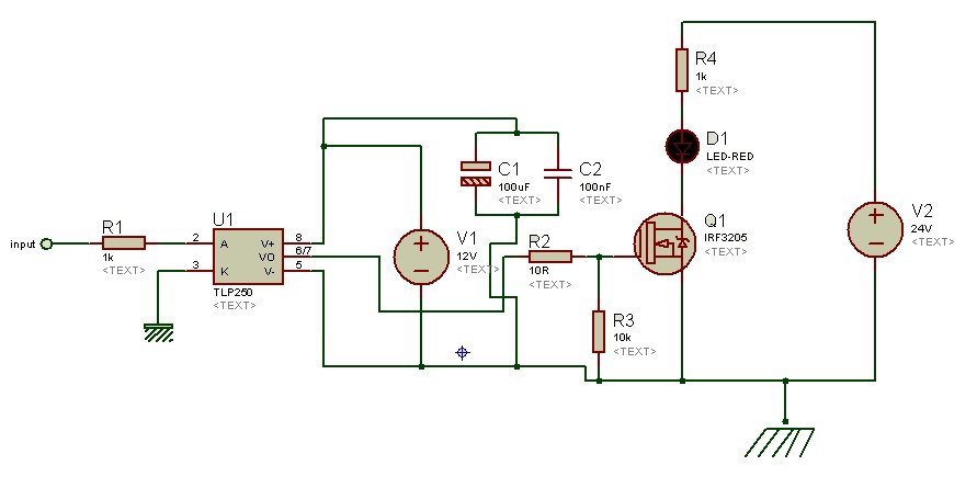
IF YOU DO NOT WISH TO SO AGREE, DO NOT DOWNLOAD, COPY, INSTALL, OR USE THE CONTENT. BY DOWNLOADING, COPYING, INSTALLING, OR USING THE CONTENT, YOU AGREE TO THE TERMS OF THIS AGREEMENT. DO NOT DOWNLOAD, COPY, INSTALL, OR USE THIS CONTENT UNTIL YOU (THE 'LICENSEE') HAVE CAREFULLY READ THE FOLLOWING TERMS AND CONDITIONS. IMPORTANT - READ BEFORE DOWNLOADING, COPYING, INSTALLING, OR USING. Excellent IFT Stability-IR Emitting Diode Has Low Degradation.These devices feature greatly enhanced static dv/dt capability to ensure stable switching performance of inductive loads. These devices isolate low voltage logic from 115 V AC and 240 V AC lines to provide random phase control of high current triacs or thyristors. The MOC3051M, MOC3052M and MOC3053M consist of a GaAs infrared emitting diode optically coupled to a non-zerocrossing silicon bilateral AC switch (triac). The gate-driver circuit is often included in the same package as the optocoupler, so two separate optocoupler-gate-driver ICs are. Another approach, shown in Figure 2, avoids the problems of high-side to low-side interactions by using two optocouplers and two gate drivers to establish galvanic isolation between the outputs. The convenience of an H-bridge is that a low. This time is also used for calculating the value of capacitor used in bootstrap circuit.An H-bridge is a circuit configuration commonly used to control the speed and direction of a brushed DC motor. The ON time and off time of the optocouplers decides the ON and OFF time of the MOSFET. So at a time only one of the optocoupler is ON and another one is OFF. The microcontroller generates two PWM signals with a phase difference of 180 degree. This resistance saves the optocoupler from high current. The PWM signal is of 5V and the 100E resistance at the input of optocoupler provide a current of 50mA. The microcontroller board used in the circuit is Arduino. For providing the input logic to the optocoupler a microcontroller is used which generates the PWM signal for this purpose. The forward current of the LED must be less than 60 mA. The forward voltage of the LED is in between 1.23V to 1.5V. The pins 2 and 3 of the optocoupler are the input pins of the LED.


The isolation is optical as in an optocoupler, the input is a LED (Emitter) and the output is a photo transistor(Detector). For isolating the input and output, two optocouplers are used.


 0 kommentar(er)
